BOYER MKIV IGNITION SYSTEM FOR 12V TRIUMPH/BSA TWIN CYLINDER – KIT00052
DOWNLOAD PDF FILE HERE: JRC 3576 BOYER KIT00052
Boyer MKIV Ignition System For 12V Triumph/BSA Twin Cylinder
JRC 3576
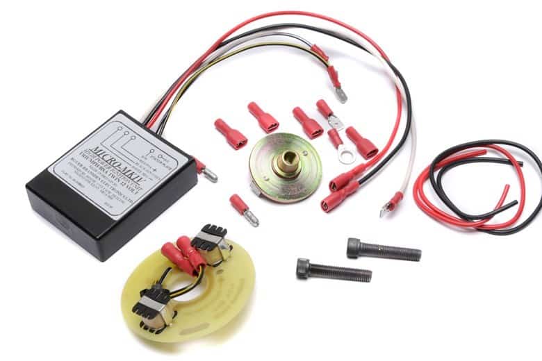
- Transistor Box (black box with wires) Part number JRC 3576A (BOX00023)
- Stator Plate (round printed circuit board with two coils) Part number JRC 3576S (STA00152)
- Magnetic Rotor (round plated steel unit with two magnets) Part number JRC 3576R (ROT00118)
- 1.25″ x 0.25″ BSF bolt (Norton), 1.25″ x 0.25″ UNF bolt (Triumph), plastic strap, coil link wire, black 1ft, coil positive earthing wire, red 1ft, terminals: 4 female spades, 1 male spade, 2 male bullets & 1 ring
WARNING THIS UNIT CAN PRODUCE HIGH VOLTAGES ALWAYS TURN OFF BEFORE WORKING ON THE SYSTEM. These instructions are a general guide to fitting the system to various machines with ignition coils, wiring, and battery in different positions; thus it may be necessary to modify the length of some wires to complete the installation. If so, all connections should be of the highest quality, twisted wires will not give a satisfactory operation.
General Fitting Instructions:
1) Remove the petrol tank and/or seat to gain access to the ignition coils, condensers and wiring.
2) For safety, remove one battery connection (or fuse).
3) Remove contact breaker plate and auto-advance unit.
4) The two wires going to the contact breakers are used to feed the triggering pulse to the transistor box and must be traced up to the ignition coils and condensers and removed from them. These are normally black-white and black-yellow wires.
5) Remove the wires going to the other terminals of the ignition coils. These will be the negative feed wires from the ignition switch.
6) Link across, using a black link wire, the negative terminal of one ignition coil to the positive of the other. Cut wire to length and fit female lucar connectors using pliers to crimp the terminals.
7) Using the red positive earthing wire, connect the positive of the first coil to a good earthing point on the frame or the positive terminal of the battery. See Fig.1.
8) Find a suitable position for the transistor box near to the ignition coils. Use the black plastic strap or tape for fitting.
9) Connect the black wire from the transistor box to the negative of the second coil. See Fig.1.
10) Connect the red wire from the transistor box to the positive terminal of the first coil – the same point to which the coil earthing wire feeds. See Fig.1.
11) Connect the white wire from the transistor box to one of the negative feed wires from the ignition switch. These were taken off the ignition coils in step (5) above.
12) Connect the black-yellow wire from the transistor box to the black-yellow wire that goes down to the contact breaker housing.
13) Connect the black-white wire from the transistor box to the black-white wire that goes down to the contact breaker housing.
14) Tape the ends of any spare wires and check all connections are good and tight.
15) Remove timing inspection cover from alternator side of engine.
16) Set engine to the full advance timing mark on compression.
17) Fit the magnetic rotor onto the end of the camshaft in the contact breaker housing using one of the cap head screws, two different threads being provided. This should be finger tight; if the thread is too long a small amount should be cut off the end.
18) Hold the stator plate in the contact breaker housing and with it half way along its adjustment slots, turn the magnetic rotor on its taper until the magnets line up through the appropriate timing hole. This must be done without turning the engine. See Fig.2.
19) Tighten the rotor cap head screw and re-check engine position and rotor alignment.
20) Fit stator plate with the standard pillar screws.
21) Connect the black-yellow and black-white contact breaker wires to the corresponding wires on the stator plate, using the male bullet connectors.
22) Refit tank, battery and seat.
23) Start engine and run for 4 to 5 minutes to warm up. Connect the strobe lamp and time with the engine running up to 5000 R.P.M. This is done by moving the stator plate on its slotted holes. If the timing is not obtainable before the end of the adjustment, the magnetic rotor will need to be slackened off and moved a small amount until the timing can be obtained.
24) Refit timing and contact breaker cover. The timing is now set and requires no further adjustment, but ignition coils, switch, battery, HT cables, plugs and plug caps must be in good order.
General Data
1) This unit can run positive or negative earth as long as the ignition coils are fed from the positive supply.
2) The working voltage is 10 to 16 volts.
3) The maximum ignition coil current through the unit must not exceed 5 amps. This current is dependent on the coils used.
4) For low compression engines two 12 volt coils in series are satisfactory, but for racing and high compression engines two 6 volt coils in series or one 12 volt double ended coil with a primary resistance of 3 to 4.5 ohms will give the best results.
5) Ignition coils can go short circuit to earth if the mounting clamps are too tight. If you are not sure mount them in rubber.
6) Shorting out the ignition coils can damage the unit. The coil current should drop to zero after 5 seconds, without triggering.
7) The resistance of the coils on the stator plate should be 66 ohms each, and the magnetic rotor should have the south poles of its magnets pointing outwards.
8) This unit can be adapted to work on many types of engine, if firing is required every 180° camshaft or 360° crankshaft driven.
9) This unit will drive two coils up to 10,000 sparks/minute.
10) Typical working advance range is 10° at 2,500 R.P.M. camshaft.
11) The unit draws 0.05 amps over the normal coil consumption and the peak primary voltage is regulated at 400 Volts.
12) This unit must always be operated with the frame or chassis acting as an electrical return, whether positive or negative earth. Also, if the engine is rubber mounted a good earth strap must be provided.
13) This unit will operate from an alternator, rectifier, zener diode and capacitor battery-less system, but kick-starting may be more difficult. (IF THE ZENER DISCONNECTS WHEN THE ENGINE IS RUNNING THE IGNITION WILL BE DAMAGED) For this reason we recommend our POWER BOX UNIT. This is voltage controlled and cannot damage the system.
14) Trim wiring to the correct length; never coil spare wire up as this can affect the correct running of the ignition system. If possible the wires from the stator plate should be run separately from the main wiring loom.
15) With this system both spark plugs are fired at the same time, thus if the engine only runs on one cylinder the fault can only lie with the mechanics of that cylinder, spark plug, lead or ignition coil, not the transistor box or stator plate.
Fault Finding – Technical Help
I Have No Spark
Check the battery has power, switch on headlamp; this should stay bright for one minute
The Fuse Keeps Blowing
Replace the fuse with a 21 watt indicator bulb. As the electrical circuits are switched on the bulb will glow dimly, if a faulty circuit is connected the bulb will glow brightly. If the bulb glows bright with nothing switched on, remove wires from components in turn until the bulb goes out, the last one removed will be the area of the faulty circuit.
How Do I Check The Ignition Unit Has Power?
Using a powerful bulb and a voltmeter check the main power feed in to the ignition unit. This would be the wire from the ignition switch or kill switch. A 21 watt indicator bulb with wires attached makes a very good test lamp, a voltmeter can be attached in addition. With this connected between the frame and ignition feed wire, the lamp should glow brightly, if dim or varying try moving the fuse holder, wiring, handlebars, to locate and faulty connections. Also test between the feed wire and the wire used to ground or earth the system, as a poor earth connection can be most difficult to find. The bulb draws similar current to the ignition and is a more useful test than the voltmeter.
Most older MKIII ignition units will produce a spark when switching the ignition on or off, if this is so and sparks are produced on all cylinders then the ignition coils must be in good order. If one or more fail to spark a coil could be faulty. On four cylinder machines try disconnecting one coil at a time, and switching on and off, checking for sparks. On other machines the coils are used singularly or connected in a chain in series. One coil failing can stop sparking but if it becomes short circuit to its case the coils after it in the chain will stop working. It is possible that a working coil is shorting to the case, and stopping the other coils in the chain from working. This is very common when a Lucas coil is over tightened in the metal clamp; the case becomes crushed and touches the windings inside. This can occur when the coil warms up. The Micro-MKIII, Micro-Digital and Micro-Power units all turn off when not being triggered, therefore it is best to carry out the next test as you may not always have a spark on turning on and off.
I Have Sparks On Switching On And Off But Not On Cranking
Disconnect the wires from the ignition box that go to the stator plate. With the ignition on, touch these two wires together, making and breaking should produce a spark at the spark plugs. If sparks are present then the ignition box is most likely to be in good order, if none are present the box is faulty. Check that the rotor magnets are running within the two metal pole pieces. On British machines, if necessary the rotor can be moved out slightly by placing a thin metal shim around the taper. The ignition will not fire if turned by hand at less than 200 RPM.
How Do I Check The Stator Plate?
A full visual check of the condition of the circuit board and coils looking for loose or broken parts. Check for signs of the rotor touching the solder connections. Using a multi-meter check the resistance of each pickup coil and then the total resistance across the wires or terminals. With the meter still connected, run your fingers round the coils, if the resistance changes there could be a broken winding inside.
How Do I Check The Rotor?
The magnets should just hold the weight of the rotor when placed against a piece of steel. Check the marking spots are the same way round. All magnets should have a similar amount of strength.
I Have Sparks On Cranking But It Won’t Fire
Check the stator wires do not change colour in the wiring loom, as swapping these will make the ignition fire over 50 degrees retarded. With a digital system check you have suppressed plug caps fitted of approx. 5000 ohms. If timing has just been done, don’t forget that the timing angle on the camshaft is half of the crankshafts (i.e. on a 650 triumph full advance timing is 38 degrees crankshaft but is set at 19 degrees on the camshaft).
I Have Continuous Sparking Without Cranking The Engine
A poor battery with a battery charger connected or one or more bad cells. A high resistance in the wiring circuit or earth return. Check that the engine is earthed back to the frame and battery circuit. Plastic coated frames must have a good earth return to the engine case. A wrong type of ignition coil with a very low primary resistance, this will draw a very high current and produce a large volt drop across the wiring. The unit will keep turning on and off generating a chain of sparks.
The Engine Runs Fast At Idle, Kicks Back on Starting
Poor fuse connection or wiring running low or variable voltage to the ignition. As the alternator charges into the system with increasing speed the problem can clear.
The Engine Runs (Poor Starting) But Misfires
Poor ignition switch or bad connection vibrating on and off. Spark plug caps open circuit (suppressors broken up).
How Do I Maintain My Battery?
Conventional batteries
Regularly check the battery, terminals and acid level. If the level drops below the lower level top up with distilled water. Always charge the battery fully is it becomes discharged. When the battery is not in use keep it fully charged and the acid level up to the upper level. Batteries not in use should be checked once a month.
Maintenance free batteries
Even so called maintenance free batteries need to be maintained!
All batteries should be voltage checked once a month or more often if they are not in use as batteries discharge quickly especially if they are stood for long periods or the machine has an alarm fitted. If the battery voltage drops below 12.4 volts the battery needs charging, a fully charged battery will read 12.8 – 13.0 volts. If the battery reads 11.5 volts or less the battery is over discharged and the internal resistance may be too high to charge at a normal charge voltage.