Download the PDF here Trident install
Trident/Rocket 3 Throttle gantry conversion.
JRC 14-315A
Thank you for your purchase of
JRC Engineering carburettor conversion for the BSA and
Triumph 3 cylinder motorcycles 1968-1974 A75
and T150. Please note the T160 uses a different
adaptor set. These instructions should make the
job of changing carburettors easy. If you do not
feel qualified to do this job please contact us and
we can refer you to a qualified professional in
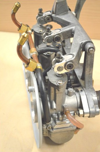
your area. Figure 1 shows the completed assembly.
Step 1. Disconnect the battery to remove any
chance of a spark igniting fuel.
Step 2. Remove the stock fuel lines from the fuel taps, remove the fuel tank mounting bolts at the front and rear of the tank. Be careful not to inadvertently
turn the fuel tap on while removing the fuel tank. Set the tank in a safe place away from
the work area. Please note that gasoline vapour can travel a long way and can
be ignited by a dryer pilot light and flash back a long distance. Always work in a
well ventilated area and be very careful with gasoline.
Step 3. Slack the hose clamps that secure the gantry to the cylinder head. Remove
the throttle cable from the gantry. Remove the stock air box by slacking
the two securing bolts. Lift the carburettor up gently until the gantry comes
away from the rubber inlet manifolds.
Figure 1
Step 4. Take the carburettor set outside and turn upside down to drain the
remaining fuel from the float chambers. Do this in a well ventilated area.
Step 5. Remove the six screws securing the carburettor tops to the bodies.
Loosen the throttle rod lock nuts and unscrew the throttle rods from the gantry
pivot. Remove the fuel line assembly from the old carburettors. Remove the 6
half inch nuts that secure the carburettors to the gantry and separate the carburettors
from the gantry.
Step 6. Remove all standard carburettor
control mechanism but retain pull wires
trunnions and adjusters, these will be reused.
The kit consists of 3 sets of components
comprising of one each of the following,
machined aluminium link, countersunk
top hat bush, threaded top hat bush
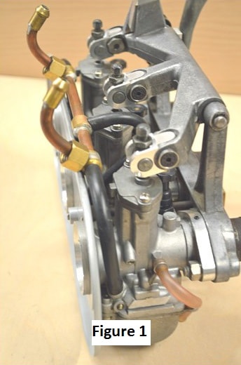
and M5 countersunk screw. The pull wires
may need the extra nipple removing as in
figure 2.
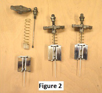
Figure 2 showing pull wire on left with nipple removed, other two assembled
ready to be installed into carbs.
Step 7. Figure 3. Shows the method of
assembling the components, when
tightening the screw make sure the extension
piece is fully positioned in the
bottom of the gantry, owing to the hand
finished nature of the gantry it may be
necessary to fettle the external radius
to enable the proper fitting of the top
hat bushes to allow the screw to align.
If the centre one is assembled first it is
easier to gain access the screw.
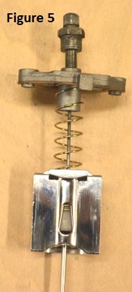
Figure 4-5
Tighten the countersunk screw fully (Figure 4) ,
when doing this it is suggested that you align
one flat of the hexagon vertically to assist
clearance of the radius on the inner corner
of the casting. You might like to apply some
thread lock to the screw for added security.
The pull wires, adjusters and trunnions are
assembled as they were in the original set-up, see picture (Fig.5)

Step 8. Drop the slide assembly into the carburettor body making sure the
throttle needle enters the needle jet hole in the bottom of the carburettor bore.
Secure the top with the Phillip’s screws to the carburettor body. Bolt your new
JRC carburettors to the gantry using the O rings provided. Tighten the 6 securing
nuts to just past snug, do not over tighten.
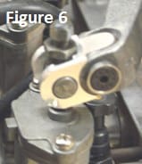
Slide the trunnions into the gantry
(Figure 6) arm with the slot outward. Insert the lifting rods through the new
gantry extensions and loosely tread the lifting rod down until the throttle slide
is completely closed and no light can be seen through the inlet of the carburettors.
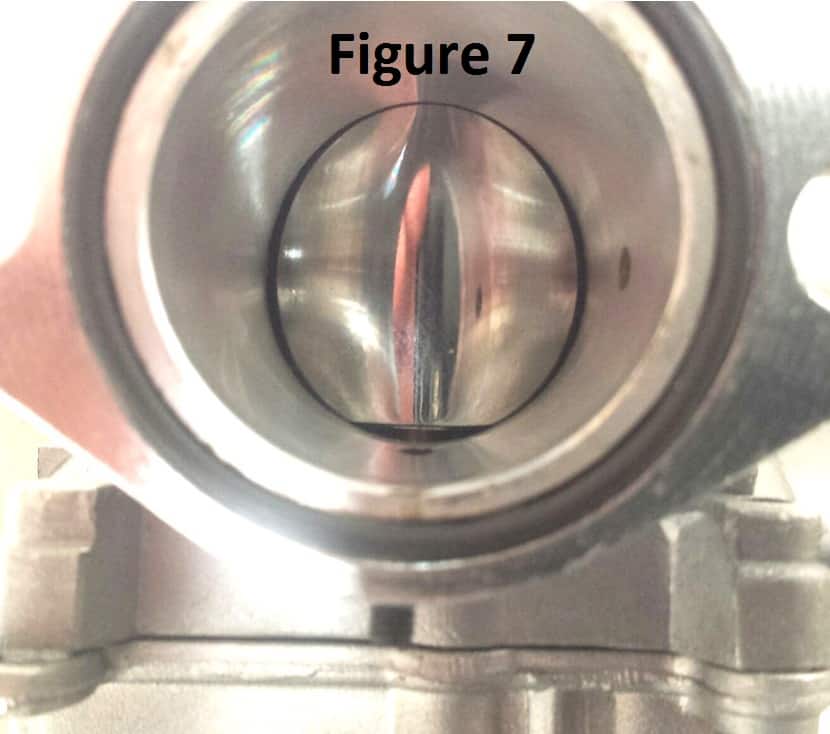
Now turn the idle screw on the gantry until a slight gap can be seen at the
base of the throttle slide and the carburettor bore (Figure 7 ). Adjust the throttle
rods on all 3 carburettors so that the gap is identical for all 3 and lock down the
larger throttle rod lock nuts.
Step 9. Using care slide the gantry back into the inlet manifold rubbers. It is
recommended that you replace these rubber manifolds if they have become
hard or are cracked. The Triumph part number is 70-9060 and are available
from us or a reputable dealer. Do not use radiator hose as it is not suitable for
use with gasoline. Connect the throttle cable to the gantry.
Step 10. Fabricate fuel lines using the fuel hose and clamps supplied along
with the Tee fittings supplied. Always use clamps with fuel hose. We have left
the fuel line Simi finished so you can adjust it to your fuel tank style.
Step 11. Remove the rubber grommets and steel rings in the
air box. Install the large O rings supplied with the kit on the
mouth of each JRC carburettor and install the air filter assembly
leaving out the thick grommets and sleeves. By removing
the large grommets originally on the filter the air filter can
move forward enough to compensate for the slightly longer
JRC carburettor.
Step 12. Reinstall fuel tank. Attach fuel lines and turn fuel on
checking for any leaks. Reattach battery leads.
To cold start pull up on the large black knob on each carburettor
(Figure 8) .
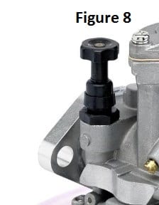
These enrich the mixture for cold
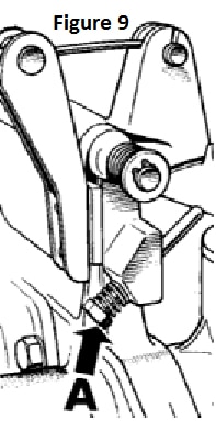
starting. Start the engine and allow to come up to operating
temperature. Adjust the idle speed using the large adjuster
on the original gantry (A).
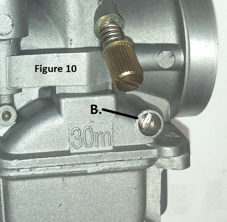
Turn the air screws ( Figure
10- B )on the side of each
carburettor slightly in or
out until the idle speed
picks up a bit. Do this for
each carburettor and then
set the idle speed to 6-700
RPM using the larger gantry
adjuster (A ) figure 9.
It is advisable to turn fuel off whenever the engine
is not in use.