ELECTREX WORLD IGNITIONS
Fitting Instructions for the internal and external rotor CDI kits.
To learn more about how AC CDI ignitions work scroll down past the instruction links.
External Rotor Kits:
JRC EW2 Rotor Nut Specs Click Here
Ignition Timing Rotor Markings Update:
Step 6. (EW1 Instructions) and Step 7. (EW2 Instructions)
Note: The new rotor RO100-03. has degree markings to make timing set-up simple. With the piston set at TDC (Top Dead Centre) align the correct degree marking with the blue punched dot on the stator plate, see Fig. 5. This sets the full advance X°. This can be checked by using a strobe light –
where the ‘FA’ mark on the rotor should align with the blue dot on the stator. For the older rotor RO100-01 there will only be the “FA” mark on the rotor. With the piston at TDC (Top Dead Centre) align FA with the blue or red dot on the stator plate.
Internal Rotor Kits:
Other EW Product Instructions
Troubleshooting:
All kits from Electrex World are supplied with 5K ohm resistor plug caps. These should be used with the ignition for optimum results. Failure to do so may result in ignition fault and misfire conditions.
Ignition Box Advance Curve Click Here For Chart
What is an AC CDI ignition?
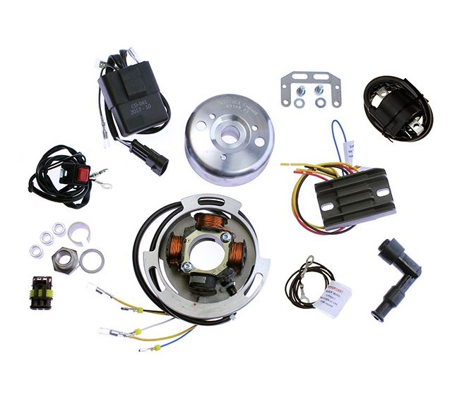
AC CDI ignitions are a type of self generating capacitive discharge ignition. They can be found on almost all internal combustion engine powered lawn care equipment made after 1980. Their simplicity has made them an idea choice for small engine ignitions and in turn the motorsports industry. You could think of it as a solid state magneto. Power is almost always provided by a crank mounted magnet and a stationary charge coil. In the case of the Electrex World units they replace the stock Lucas alternator charging system (primary side case).
AC ignitions consist of: a charge coil, a rotor magnet, ignition module, and coil. The triggering part of the ignition is normally part of the charge coil in the form of a separate winding. This is one way that AC and DC ignitions vary from each other.
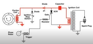
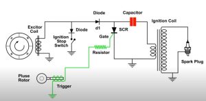
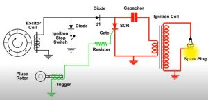
Below is a basic schematic of the function of the ignition. The exciter coil (charge coil) charges a capacitor inside the ignition module. An electrical pulse from the pulse rotor (trigger coil) controls a electronic switch which mimic contact points which fire the ignition coil.
Troubleshooting these ignitions are pretty simple. Checking charge coil continuity and output voltage at kick over. And checking for spark is all one can really do. Faults typically will be timing, grounding, or charge coil related. If the charge coil is damaged the resistance will be out of spec. Easily checked with a multimeter. Checking for spark can be tricky on some systems. The spark on these systems are typically high intensity, short duration and not highly visible at low rpm. At kickover the unit is producing the minimum charge to fire the plug. It may help to do any test work in a dimly lit workspace. Otherwise it can appear that a bike may not have spark when in fact it does. Or you can follow the advice of one of my dealers and just hold the spark plug and rest your hand on the engine. This will give you a shock and you will know without a doubt if the unit is working. This is an effective yet unpleasant method of checking the unit. For obvious reasons we don’t advise trying this if you have any heart trouble or a pace maker.
Charge coil output at kickover is typically about 30-50v AC. Trigger pulse will measure less than 5v AC at kickover. If checked by back probing, while in operation, the voltage readings will be considerably higher. Note disconnecting any lead with the unit running can cause damage to the ignition. So we advise to take voltage readings only at kickover. The charge coil is capable of producing several hundred volts at higher rpm. And the ignition is capable of delivering a nasty shock if care is not taken.
In the simple diagram below the pulse or trigger is shown as a separate component. Most units will have the trigger and exciter/charge coil as one unit. This can easily be IDed where their are 3 wires exiting the stator rather than 2. One of these wires will be a common ground and the others trigger and exciter/charge.