Lucas Alternator Manual 87 pages
Lucas Alternator Tips and Hints
The alternator system fitted to British bikes from the 1960 season is a very clever way to extract the most electrical power from the least amount of space while not having to completely redesign the primary drive. BSA fitted alternators to the B33 singles toward the end of production and to all machines in the range after 1962.Triumph used an alternator on the 5T for 1954 on and the Thunderbird from 1956. All Triumph models used alternators from 1960 on. The alternator consists of a permanent magnet rotor attached to the crankshaft and a series of 6 (single phase) or 9 (three phase) stator coils surrounding this rotor attached to the inner primary cover or directly to the main crankcase. There are a number of problems with these units but happily all are easily remedied. First let’s look at the problems.
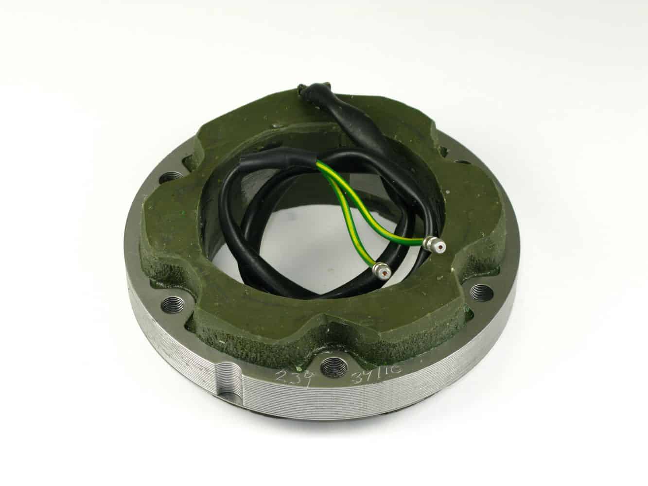
The early stators had open windings insulated from the steel ring they are mounted on by heavy card stock and a coating of varnish. With time and vibration these coils tend to work loose. This movement chafes through the insulation and shorts the coil to ground. For this reason it is advisable to replace these open stators with the later epoxy coated units. It is false economy to reuse an open stator, they will fail.
Rotors can and do become demagnetized. A rotor should always be stored with keeper shoes encasing the magnets to preserve its magnetic properties. You may store the rotor in the stator for the same protection. A rotor that has been left open for years may have lost a substantial portion of its magnetism. You can spend a load of time chasing charging issues if this occurs. In my opinion a new rotor should be used anytime the old one has been left out for any extended period. Another issue with rotors is that they may become loose on their centers. You can check for this buy clamping the rotor between two spacers in a vice and trying to turn the magnet portion. If there is any detectable play the rotor is no longer usable. These can not be fixed, don’t even try. If the rotor comes apart while the engine is running you will destroy your primary drive and risk locking the rear wheel or bending the crankshaft. Never hit a rotor with a hammer to drive it on to the crankshaft. This will also demagnetize the rotor. Check the condition of the keyway also. A loose key or a rotor loose on its center will rumble just like bad main bearings.
On later stators check the condition of the wires where they exit the epoxy coating. It is not unknown for the wires to be broken here inside the plastic insulation. It is very difficult to repair this, replacement is the best option.
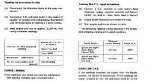
A static test can be carried out on a stator as follows. With the stator removed from the machine and the rotor not in the stator do the following test. Using a basic 12 volt automotive battery charger (new smart chargers won’t work), or 12VDC power supply, connect the terminals of the charger to the 2 leads of the stator. In the case of a 3 wire stator connect the Green/black and Green/yellow in common as one lead and the Green/white as the other. Using a flat blade screw driver check for magnetism at the poles inside the stator. There should be equal and substantial pull from each pole. If not the stator is defective. Using a VOM check for continuity between the 2 or three leads of the stator. There should be good continuity between all of the stator leads and no continuity to the outer steel ring of the stator. If one of the wires is open, that is there is no continuity or if there is continuity between any wire and the steel body of the stator then replacement is the only option.
After installing your alternator it is most important there be clearance between the rotor and stator. Check for clearance using stainless steel feeler gauges. There must be a minimum of .007” clearance. Rotate the crankshaft 33 degrees and check again. Do this one more time so you will have checked clearance at 3 different crankshaft positions. If the rotor rubs the stator it will loose magnetism and possibly overheat and come apart. If there is a tight spot try loosening the securing nuts and pushing the stator gently and retighten the nuts. If the tight spot moves when you rotate the motor either the crankshaft is bent or the rotor is loose on its center and about to fail. Test again with a new rotor to see what component is at fault. Do not try to turn the rotor undersize to gain clearance.
When routing the stator wires you must account for primary chain deflection. It is embarrassing to run out of electricity because your stator wires are cut through by the primary chain.
Be sure to separate the stator wires from the points wires if you are using electronic ignition. The AC pulse in the stator lead will bleed over to the points lead and trigger rouge sparks from the ignition. This can be difficult to diagnose and cause all kinds of tuning issues. Mount the regulator/rectifier away form the black box of the ignition.
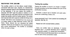
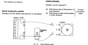
The rectifier used by Lucas converts the AC current from the alternator to DC current to run the lights, ignition and charge the battery. It consists of a series of diodes mounted to heat sinks. When installing the rectifier it must be open to the cooling air. In addition the center stud must be grounded. Be sure when tightening the rectifier securing nut to hold the bolt head on the top of the unit rather than holding it by the fins. If you rotate the fins on the bolt it is easy to damage the insulators between the plates and ruin the rectifier. A simple test of the unit can be made with a volt ohm meter. The 2 outer spades where the harness connects should have good continuity in only one direction with the spade between them. If there is no continuity or if there is continuity in both directions the rectifier needs to be replaced. The rectifier is polarity sensitive and will be ruined if connected to a power source backwards, even for a very short time.
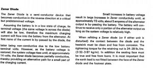
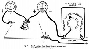
The zener diode is a brass looking affair mounted to a heat sink, usually under the tank or at the front of the bike. The diode acts like a pop off valve shunting excess current to ground in the form of heat. It is most important that the diode be in the cooling air flow and on a proper aluminum heat sink. Apply a bit of dielectric grease between the diode and heat sink to keep corrosion from interfering with heat transfer. Zener diodes are polarity sensitive so if you connect them backwards they will be quickly ruined. A simple test of a diode can be done as follows. Using a volt ohm meter check for continuity across the Diode. There should be some continuity in one direction and none in the other. If there is continuity in both directions then the diode needs replacing. Next using a 12 volt automotive battery charger connect the positive lead to ground on the motorcycle or to the mounting stud on the diode. Set your volt-ohm meter on the 10 volt scale and connect the positive lead of the meter to the spade on the diode and the negative lead to the negative charger lead. You should have a reading of ½ to 1 volt as the diode becomes conductive over 13.5 volts. If no reading then the diode may be open and needs replacement.
Don’t overlook the Lucar connectors where the harness plugs into the stator leads. I can’t tell you how many times I have found charging issues due to corrosion at the connectors. They are under the battery so are often bathed in battery acid and engine oil, not the best combination. Use dielectric grease here also to insure a clean connection.
Testing output on a running machine in this way. You will need an ammeter for the first test. Any old automotive unit will do or a Pep Boys cheapo replacement type. Connect leads to the ammeter and install alligator clips on the ends. Add this cheap tool to your tool box, it’s very handy. Remove the center Brown/blue wire from the rectifier. Connect the ammeter in series with the rectifier and the brown/blue wire that was plugged on to that terminal. Start the bike. The ammeter should show a discharge of 1-2 amps at idle speed. The needle should move to charge as you increase engine RPM to 2000. The needle should show a charge of 1-2 amps at 2200. Now switch the lights on. There should dip in charge rate followed by moving back to positive above 2200 RPM. If the needle shows no charge recheck all connections or components. If it takes 3000 RPM or more to begin showing a charge then the Rotor may be demagnetized or the stator may have 2 dead coils. Check the stator coils as described above.
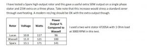
You may want to consider replacing the Lucas rectifier/ zener diode with one of the solid state units on the market. The units from companies such as Boyer or Podtronics have been around a long time and are very reliable. In recent years the Tympanium and Sparx units have become problematic. So best to avoid these two makers. New Lucas and Emgo replacement rotors and stators that have proven reliable in service. In addition these companies have taken advantage of modern components to offer 200 watt units to replace the 120W Lucas components. When using these units you must fit a solid state regulator as the standard zener is not up to the added load and will quickly fail.
by Bill Getty
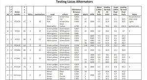
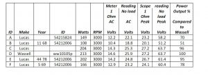
Testing procedures and technical data: