TROUBLESHOOTING DC CDI IGNITIONS
In this article we hope to cover some of the technical issues often encountered with electronic ignitions.
Definition:
DC CDI ignitions are solid state ignitions that uses a direct current power source. This can be either a battery, stock charging system (zener diode/bridge rectifier), or solid state regulator/rectifier with or without capacitor (capacitor allows for battery-less starting). All that is required is the input volt falls within the required range. We will cover this in more detail further on in the article. An AC CDI ignition generates its own alternating current power. Read more about these in our article on Electrex World ignitions. All “kit” or “CDI” references made through out this article pertain to DC CDI ignitions.
Disclaimer:
Some folks find electrical and electronic ignitions intimidating. If you are not confident in your abilities it might be best to take your machine to a shop with experience in British vehicle electrics. Better to get your bike sorted properly than potentially causing expensive damage. Failure to observe polarity can result in: a ruined wiring loom, damaged electronics, and possibly catastrophic fire. All work should be done outdoors or in a shop with fire suppression equipment at hand. Checking for spark with fuel vapor nearby has been the cause of several fires that have consumed entire workshops and bike collections. Treat fuel and ignition systems with respect and think through your actions before attempting a job.
Tech:
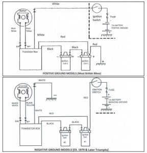
Most CDI kits are comprised of several components: a control box (module or brain), trigger plate, and trigger magnet. Some of the Tri-Spark ignition kits combine the control module and trigger plate under the points cover.
We stock most of the available electronic ignitions (listed in order by date of inception): Boyer (1969), Pazon (2005), Sparx (2006), Tri-Spark (2007) , and Vape (2010). Speaking only of the standard analog ignitions (all makers, with the exception of Sparx, offer high performance products that this article won’t address) use similar circuitry and to accomplish the same task. This task being to replace the breaker points and advance unit and mimic their functions. Elimination of the contact breaker points eliminates the need for adjustment and replacement of worn components. Some folks choose to stay with points as they like the original tech and the ability to service a bike out in the field. Both are just as reliable, in my opinion.
Triumph in 1979 came out with electronic ignition as standard equipment. The Lucas Rita ignition (first introduced in 1973) was used till the end of production of the 750 twin in 1985. Boyer Bransden came out with their famous Micro MK2 (mark two) ignition about the same time. This design would be improved upon in 1996 with the MK3 and again with the current MK4 version was released in the 2000s.
Most of the other brands of ignition available today were inspired by Boyer’s design. Each have design features that distinguish them. All operate on the same principles making troubleshooting straight forward. All work on the wasted spark principle with the exception of the Tri-Spark 3 cyl kit 0002.
Boyer Testing – by John Healy – Vintage Bike Magazine – Click here to read the article in its entirety
Scratching Box Leads (Scratch test)
With the spark plug laying on the cylinder head, Scratch the Black/Yellow and Black/White leads from the ignition control box on each other. Please Note: This test ASSUMES the battery, wiring, connections, switches and grounds are in working order. Although a lot is attributed by other web sites to this test, it is very possible for the box to be in perfect working condition and you will not see a spark at the plug. If the battery, wiring, fuses, switches, grounds, ignition coils and Boyer control box are in good working order the spark plug should fire a series of rapid sparks. If the spark plug doesn’t fire it could mean the ignition box has failed. It could also mean the box is not properly wired into the motorcycle, a coil has failed, or the motorcycle’s electrical system is not able to supply enough electricity to run the ignition. Low battery voltage – (charge battery), high resistance battery (sulfated should be replaced), compromised charging system, corroded: connections, fuse holder, electrical switches or bad grounds cause more problems than failing boxes. Note” Turning the ignition switch On and Off will fire the spark plug on most Boyer ignitions, it WILL NOT with the Triumph/BSA and Norton ignitions. The box does not turn on until it receives a trigger voltage from the timing plate. Vape brand ignitions are the same. A trigger pulse must be received from the timing plate before the coils energize. The scratch test has only proven as a reliable test on Pazon ignitions which specifically detail the procedure in their instructions. New MK4 units will spark on switching power on and through the scratch test.
I Have Sparks On Switching On And Off But Not On Cranking:
Check that the rotor magnets are running within the two metal pole pieces. On British machines, if necessary the rotor can be moved out slightly by placing a thin metal shim around the taper. The ignition will not fire if turned by hand at less than 200 RPM.
Trigger Plate (sometimes called: stator plate, or timing plate):
Connect a Ohm Meter’s leads to Black/Yellow and Black/White wires. Turn Ohm meter on and read resistance, 137 Ohms is a typical resistance for the Triumph and Norton trigger plate. The resistance of individual coils should be approximately the same. If one coil measures 66 ohms the other should also measure 66 ohms. If there is no reading on meter, the individual coil resistances vary greatly, or reading substantially lower than expected: Broken wire or coil wire insulation failure. Replace Trigger Plate.
Magnetic Rotor:
Hold each magnet of the Rotor up to a wide flat surface. Each individual magnet should be able to support the entire weight of the rotor. If either of the magnets will not hold the weight of the rotor: Replace Rotor. Detail of ignition rotor operation click here.
Loose Magnetic Rotor
Magnetic Rotor has come loose in camshaft taper. Socket head bolt has broken loose or was too long and bottomed in camshaft before securing rotor. Check socket head screw to see if it is tight. If socket head bolt is tight and the rotor still turns freely shorten screw bolt. After making sure bolt is proper length, a drop of BLUE Loctite can be used to secure the screw. NEVER USE RED Loctite in this application. The locating pin for the original automatic timing advance unit should have no effect on the magnet seating in the cam end. The magnetic rotor taper length is much shorter than the stock advance and can be left undisturbed.
Securing Wires
If you experienced broken wires, especially with a Norton, securing the wire leads to the plate securing stud with a small Tie-Wrap will relieve the tension on the wire. On Norton, extra slack in the wire is required between the motor and the frame to absorb the movement of the isolastic motor mounts. Form a “J” loop with the wire where it goes from the motor to the frame
Timing Plate Wires
The polarity of the timing plate wires is important. The Black/Yellow and Black/White wires must be connected color to color. Is the Black/Yellow wire on the timing plate connected to the Black/Yellow in the wiring harness. Is the Black/Yellow wire on the Ignition box connected to the Black/Yellow in the wiring harness. When these wires are connected incorrectly, the ignition advance feature will not work. It will be fixed at full advance. Also, the box will fire 70° from where you want it to. Instead of the ignition firing as the magnet approaches the coil pegs , it will fire the same distance away, after it has passed the coil pegs. Thus you will have to move the rotor in the camshaft 70° in the direction of rotation to get the timing correct.
Checking Coil Primary Resistance
All the ignitions discussed use the wasted spark design. One spark at BTDC compression stroke to fire the fuel/air mix. The second or wasted spark occurs at BTDC exhaust stroke. The design allows for use of a single dual lead coil or two OE style cylinder type coils. The resistance of the primary side (low tension side) must fall within the range specified by the manufacturer. With two OEM style coils the primary resistance is added up and should be within 3-5 ohms for the pair.
6 volt Lucas, PVL coils will have 1.9 ohms resistance, Two of these Taiwan 6 volt coils in series will have approx. 3.8 ohms resistance Two 12 volt Taiwan coils in series will have approx. 9 ohms resistance. Over tightening coil brackets can cause the coil’s primary windings to short (the meter will show a lower resistance than expected). This will cause the coil to draw a lot of current through the control box. It is common for the box to fail to work after such an event. A box with this type of failure will often have a bulge that indicates the coil driver was over heated.
12 volt Lucas or PVL coils will have 3.8 ohms resistance
Primary and secondary coil resistance varies with the brand and model of coil. Refer to manufacturer for resistance readings of your coil.
The condition of the battery in the ohm meter will effect ohm meter readings. If there is any doubt about the condition of the battery it should be replaced before testing coils.
Other issues:
Bike runs for a short time and quits. Is the box faulty? We rarely see boxes that have intermittent spark. When boxes fail they quit sparking. Ignition boxes will either spark or they won’t. There are two probably causes for this: a wiring issue that results in a connection that opens after getting a bit of heat into it, or a battery/charging system that falls below operating voltage. One common fault is the handle bar mounted kill button. The 71 and later bikes had bar mounted kill buttons that were part of the switch gear. These are especially prone to corrosion and can create problems. Coils issues are uncommon but do happen. If one coil has a problem it will result in a loss of spark (coils are wired in series on twins and some triple ignitions).
No spark or loss of spark. Has the box failed? 90 percent of the returned units we test will spark fine on our test rig. The culprit is often the wiring and connections on the bike to the ignition box. A bad ground can also cause this (common on plastic coated aka powder coated frames). Ground leads, and their contact surface on the frame, should be free of paint and corrosion. The engine should have its own ground if the frame has been powder coated.
I don’t get any voltage at the coils on my multi meter. The ignition coils are only energized during running by the ignition box. With the bike static the coils may receive power for 1-4 seconds upon powering up the bike. Voltage will fall to zero as the box switches off power to save the battery. Wiring up a test light in parallel with the the coil power wires will allow you to see that the coils are receiving power as designed.
How do I wire a kill button? See are article dedicated to this subject. Installing a Kill Button On Electronic Ignitions
Misfire During Riding. A misfire is often related to heat. If one of the coils gets too hot this can occur. Also some ignitions may develop a misfire or strange behavior during running due to the charging system. Ignitions don’t like AC present in the charging system. Tympanium regulators are notorious for leaking excessive AC. Before we discontinued the Tympanium unit we saw testing output of 13+ volts AC (and 15 volts DC). This AC voltage can be interpreted by the ignition box as trigger pulses. The result being a misfire. In some cases AC will ruin the ignition box as in the early Boyer MK4 kits. On bikes without a battery this type of issue can be exaggerated as batteries tend to act as a filter. There are also possible issues with radio frequency interference so it is recommended to run 5k ohm resistor caps with electronic ignition and solid state charging equipment. Click here for info on checking for AC voltage.
Checking Timing With Strobe. Some modern timing strobes will give odd readings creating much confusion of actual timing. If you experience an anomaly while strobe timing try swapping for a simple white light (xenon) strobe, powered from a separate battery.